Küssnacht Southern Bypass – Support Measures for a Shallow Soft Ground Tunnel Under a Built-Up Area
 Credit/Quelle: INGE Küssnacht
 Credit/Quelle: INGE Küssnacht
 Credit/Quelle: INGE Küssnacht
 Credit/Quelle: INGE Küssnacht
 Credit/Quelle: ARGE Tunnel Burg, Küssnacht
 Credit/Quelle: Tiefbauamt Kanton Schwyz
 Credit/Quelle: Dr. Heinrich Jäckli AG
 Credit/Quelle: INGE Küssnacht
 Credit/Quelle: Züblin Spezialtiefbau
 Credit/Quelle: (3) Züblin Spezialtiefbau
 Credit/Quelle: Züblin Spezialtiefbau Ges.m.b.H.
 Credit/Quelle: Züblin Spezialtiefbau Ges.m.b.H.
 Credit/Quelle: Züblin Spezialtiefbau Ges.m.b.H.
 Credit/Quelle: Züblin Spezialtiefbau Ges.m.b.H.
 Credit/Quelle: Züblin Spezialtiefbau Ges.m.b.H.
In autumn 2017, excavation of the bypass tunnel around the centre of Küssnacht, Switzerland, had to be stopped due to obstruction of the works by heavy slurry inflow and a cave-in. Intensive investigation of the causes, reassessment of the existing support concept and a new plan produced by the project engineers and the tunnelling contractors for safe tunnelling under Küssnacht finally enabled the resumption of excavation works in February 2018. As auxiliary pre-support measures in addition to the originally planned pipe umbrella, preventer-equipped grouting and drainage holes were bored and a horizontal jet grouted sealing curtain was provided. The excellent collaboration of all project parties thus created the preconditions for the successful breakthrough on 29 May 2019.
1 Introduction
The first section of the southern bypass around the historic village centre of Küssnacht am Rigi in the Canton Schwyz is to be completed by September 2020. The objective is to relieve the historic village centre of traffic. The project is financed by the Canton Schwyz and the council of Küssnacht. The client is the Canton Schwyz, represented by the civil engineering office. The total cost of Section 1 (incl. land purchasing) is about 126 million Swiss francs (about 120 million euros). The key structure of the bypass project is the Tunnel Burg, which runs through soft ground below the existing buildings with shallow cover. Tunnelling encountered unexpected ground conditions, which made necessary an adaptation of the auxiliary construction measures.
2 Project Description
2.1 Alignment
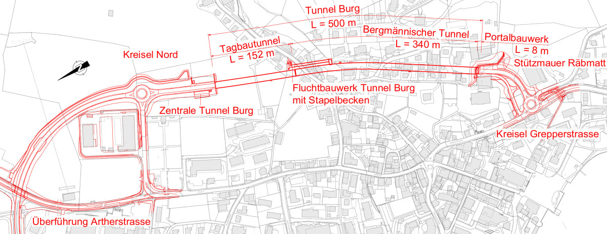
The southern bypass around Küssnacht starts to the north of the village centre at the Chli Ebnet junction (Fig. 1, left bottom) and passes under the existing main road in a curved cutting. About 120 m from the north junction, the Tunnel Burg with a total length of 500 m starts, of which about 150 m are constructed in cut-and-cover.
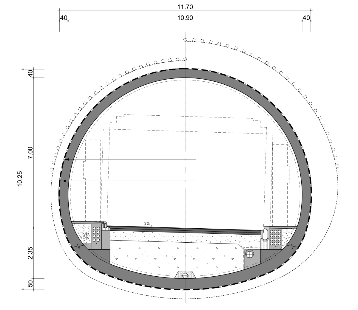
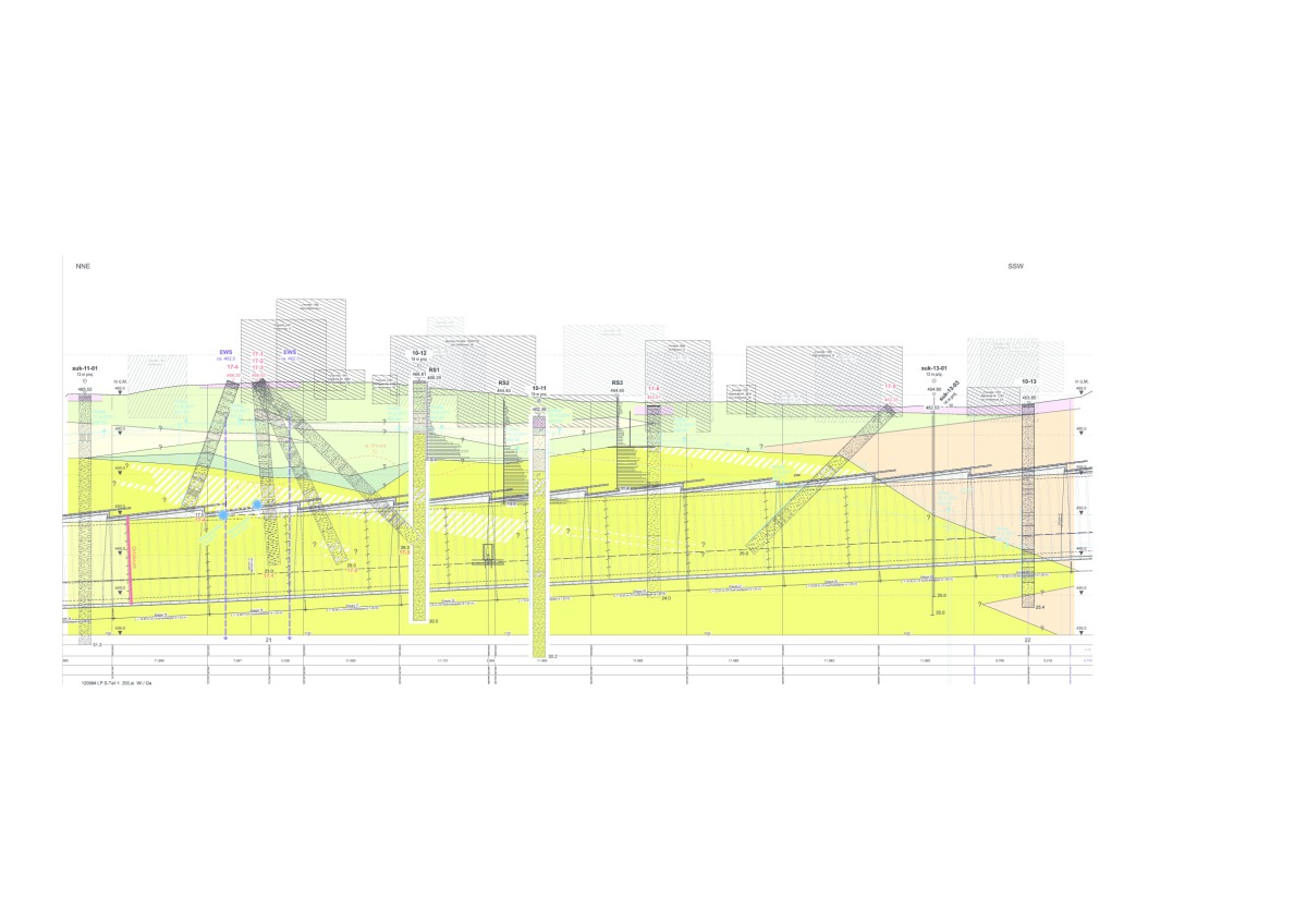
The tunnel houses one lane in each direction. In the vertical profile (Fig. 2), it has a deep point reached from both portals with ramps at a gradient of 5%. The tunnel mostly lies below the groundwater table and is built with complete waterproofing against water under pressure. Fig. 3 shows the standard profile of the Tunnel Burg.
2.2 Geology and Hydrology
The conventionally excavated tunnel section passes almost completely through glacially preloaded geological units, which are described as lacustrine deposits and gravel complex.
The lacustrine deposits mostly consist of lean clay, which shows a stiff to semi-solid consistency due to glacial preloading. In the lacustrine deposits are bedded intercalations of silty sands, which are very densely consolidated. The lacustrine deposits have high strength and very low permeability.
In the southern section, alluvial sediments (silty, partially organic sediments with very low consolidation density; see Fig. 2) were forecast above the tunnel, which were not however predicted to affect the tunnel. This forecast had to be revised during the construction period despite the high density of exploration boreholes. The location of about 18 boreholes in the area of the conventionally exvated tunnel had been decisively influenced by considerations of surface accessibility in the built-up area.
The also glacially preloaded gravel complex consists of intercalations of sandy-gravelly and sandy layers with thicknesses in the range of decimetres to metres. The consolidation is also very high. The beds found in a step slope on the surface show an only apparent cementation.
2.3 Tunnel Burg: Construction Design
and Tendering
Directly after the start of tunnelling from the northern starting cut, the mined tunnel section passes under the Seebodenstraße, the village stream running in a culvert, and various adjoining buildings with a minimum cover of about 4–5 m, but only 1.5 m from the invert of the stream. The maximum cover is about 17 m. There are buildings on the surface above almost the entire length of the mined tunnel section.
The tunnel lies in the lacustrine deposits, which are impermeable and act as an aquitard, under the groundwater table; the clay is water saturated. In the gravel complex, the water table is in the lower half of the profile and was lowered using filter wells during the construction phase.
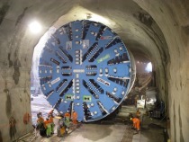
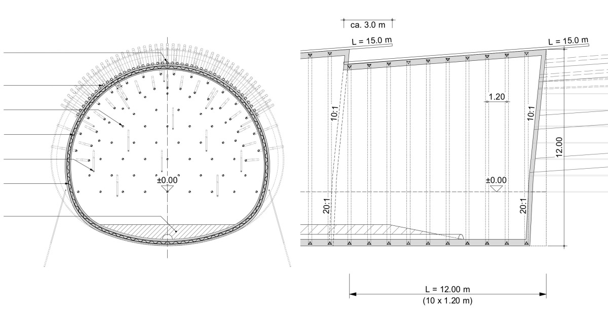
In the course of construction planning, the most important hazard scenarios were considered to be surface settlement and collapses to the edge of the excavation and in the face, or cave-in. This was countered in the selection of a tunnelling plan with full-face excavation with rapid ring closure and the provision of systematic auxiliary construction measures. The maximum ring closure distance was specified at 6 m. Excavation was carried out under the protection of a pipe umbrella (Fig. 4).
Systematic face anchoring served to secure stability and reduce the settlement trough ahead of the face. In order to drain any water-saturated sandy lenses in the lacustrine deposits, systematic pre-drainage was provided with PVC-U filter pipes (slot width 0.6 mm).
The pipe umbrella was set every 12 m, with an axial spacing of the pipes of between 30 and 35 cm at the start of a stage and an overlap of the pipes in the longitudinal direction of 3 m. The face anchors were 20 m long and the drainage holes 18 m long. Excavation was carried out in round lengths of 1.2 m, followed by support with mesh-reinforced shotcrete and lattice arches (3G-150/20/30).
Systematic monitoring of deformations in the tunnel, in the ground and on the surface was part of the plan. In the crown pipe of the pipe umbrella, deflection was monitored in real time with a chain inclinometer. In the tunnel, deformation of the temporary support was also measured with tacheometer and deformation of the face with an RH extensometer. On the surface, the surface and building levels were monitored with automated tacheometer, water levels and manual levelling. Deformation of the ground was also monitored with combined inclino- and extensometers in boreholes above and next to the tunnel.
3 Construction
3.1 Preliminary Investigations
After the start of tunnelling, preliminary investigations of the suitability of the face anchors and for the grouting of the pipe umbrellas in the lacustrine deposits were carried out in the construction pit for the cut-and-cover tunnel. This showed that the bonding between anchor mortar and lacustrine clay only permitted a relatively low force transfer in the magnitude of 50 kN/m. It also turned out that the lacustrine clay is practically impossible to grout.
3.2 Northern Tunnelling Start
In September 2016, ground was broken at the north portal, the starting pipe umbrella and the face anchors having already been installed from the secant bored pile wall. On the next day, the north advance started. Excavation was carried out with a tunnel excavator and the tunnel sides were supported with mesh-reinforced shotcrete after every round. This tunnelling plan proved successful. The prevailing ground consisted largely of lacustrine clay with stiff to semi-solid consistency, which could be easily cut by the excavator. Due to the high cohesion of the material, a full-area top heading could be broken out with geometrical precision. After a period of familiarisation, a rhythm was found: one week of excavation with support and one week of pipe umbrella and face anchors for the next stage.
3.3 Regular Northern Excavation
The plan intended excavation of the complete tunnel from north to south, with only one stage in the other direction from the south portal in order to cut through the glancing excavation support wall in advance and thus shift the breakthrough point into the ground. The works in the northern advance proceeded as planned. Deformations at the surface were however 4–5 cm, corresponding to values calculated for unfavourable ground parameters. Thanks to the fully automated monitoring, the causes and interactions could be detected promptly. It turned out that the ground behaved very softly as the tunnel advanced. In order to prevent or minimise damage to existing buildings on the surface, the ring closure distance was reduced and a restricted advance rate was specified. This enabled waiting for the stiffness development of the closed shotcrete ring and thus minimised settlement. In parallel, the pipe umbrella was installed in the tunnel from the south and the cut-and-cover section constructed, and the associated excavation stage was excavated and supported.
3.4 Stoppage of Northern Advance and
Resumption of Opposing Advance
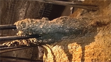
At the end of June 2017, slight water and waterborne material ingress was noticed as the face anchors were drilled for stage 15. The last metres of a 20 m long borehole encountered aquiferous beds. The water ingress could be stopped by setting a packer and grouting with cement. The associated advance in stage 15 was carried out with great care. Slight water ingress already occurred during the opening of the first round. During
excavation of the second top heading round, the following excavation was stopped due to heavy water ingress between the pipe umbrella pipes for the next round, and the northern advance was stopped on 12 July 2017.
While measures for the continuation of the northern advance were still being clarified, a decision was made to use the stoppage time productively and start construction of the inner lining from the northern end. On the southern side, the opposing advance, which already had been taken as far as originally planned, was resumed.
3.5 Stoppage of the Opposing Advance
Already in the first round of stage 28, it was noticed that the gravel showed an increasing tendency to trickle out due to the closely spaced grain size distribution. In order to maintain working safety, the excavation of the top heading was divided into several partial areas, and anchor plates and reinforcement mesh was used to strengthen the face.
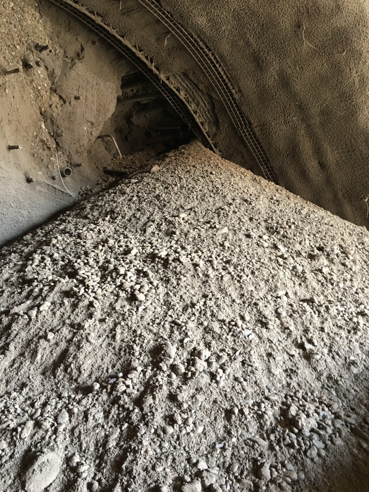
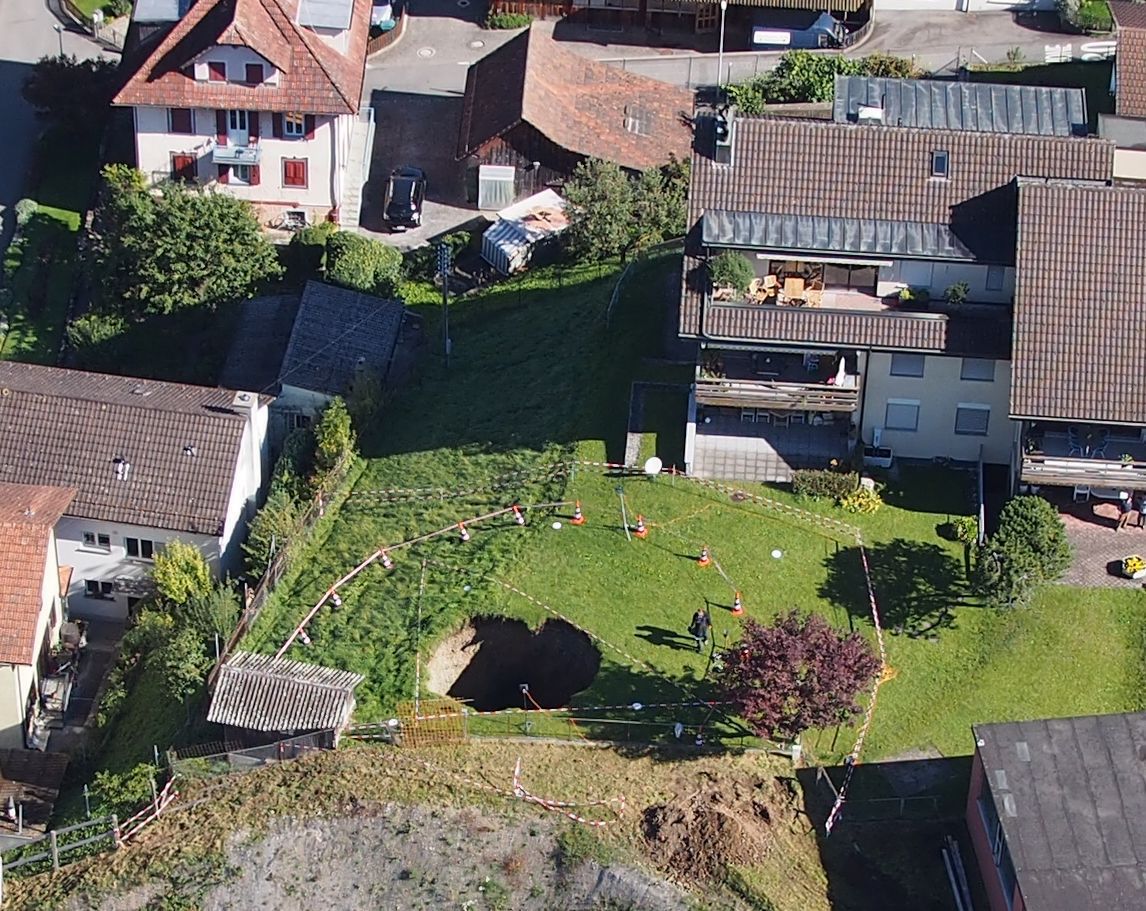
During excavation of the second last round in the opposing stage 28, a collapse occurred through the pipe umbrella pipes on 20 September 2017 (sand glass effect, Fig. 5). The collapse of the cohesionless material continued for about 30 minutes and led to a cave-in of the 17 m overburden. The collapse funnel had an estimated volume of 350 m³ and reached a diameter of 5 m at the surface (Fig. 6). The face and the temporary support remained stable, which restricted the incident so that no damage occurred to buildings on the surface.
The cave-in funnel was immediately supported, filled from above and then grouted. This stopped the southern advance until a decision could be made how to proceed further.
3.6 Search for Solutions
It was clear for all project parties that tunnelling could not be resumed without additional support measures. The following requirements were drawn up for the new tunnelling concept:
The pipe umbrella should be additionally sealed so that no more material could trickle through.
The tunnelling plan should be applicable both for the main advance and the opposing advance.
No change should be made to the existing structural concept. Additional measures should be provided.
In the discussion of measures, ground freezing and grouting to consolidate the ground were both rejected. Consultant, client and contractor rapidly agreed that horizontal jet grout columns were most suitable to seal above and between the pipe umbrella pipes. Since the jet grout columns would only be assigned a sealing function and no structural arch function, the practically difficult grouting of the lacustrine clay could be avoided. Züblin Spezialtiefbau Ges.m.b.H. was appointed as sub-contractor to the JV Tunnel Burg to carry out the jet grouting.
4 Repair Works and Adaptation of the Auxiliary Construction Measures
4.1 Additional Investigation
In the course of the clarification process at the northern end as well as on the southern end, new boreholes and a supplementary geological-geotechnical report were ordered in order to investigate the causes of the uncontrolled water ingress.
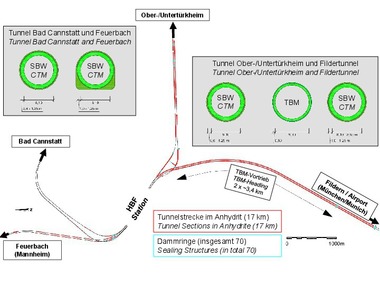
The supplementary geotechnical investigations showed that above the section of advance stages Nos. 15 to 17 is a depression filled with aquiferous stream debris of gravel and sand, which was not known of before due to the lack of appropriate exploration. This depression is marked in dark green in Fig. 7.
The preloaded lacustrine deposits (yellow) also contain cohesionless zones of silt and fine sand (hatched yellow-white), which permit water flow. Such cohesionless zones were indeed formerly known but they turned out to be unusually thick, up to 4 m, in the section of advance stages Nos. 15 to about 19 – and thus immediately underneath the depression. In the area of the boreholes, the cohesionless zones were sometimes in a fluid state due to slurry outflows.
4.2 Adaptation of Tunnelling
Considering the findings of the supplementary geological-geotechnical investigations, groundwater lowering was carried out using several filter wells from above ground for the northern advance.
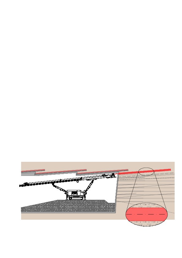
In the tunnel, drainage holes were drilled ahead of the tunnel and additional grouting was ordered in the area of the suspected origin of the slurry ingress. Horizontal jet grout columns were provided along the sides of the excavation (Fig. 8) in order to consolidate the areas between the pipe umbrella pipes and hinder ingress of slurry or cohesionless soil. Some horizontal jet grout columns were also placed within the face since smaller collapses and local instabilities even occurred after excavation under the protection of the jet grout screen.
5 Technical Performance of Additional Auxiliary Construction Measures
5.1 Grouting and Drainage Drilling
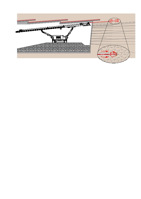
In order to stabilise and fill the voids created by soil loss due to the slurry ingress in advance stage 15 (northern advance) and to stabilise the collapse funnel in the southern drive, 20 m long cased grouting holes were drilled ahead of the tunnel in the crown. By installing manchette tubes, these areas could be treated as required with low pressure grouting.
As another measure for the advance stages in the lacustrine deposits, the prevailing water pressure above the tunnel crown was checked and reduced if required with drainage holes in a fan pattern.
In order to counter the expected water ingress during drilling, appropriate protection measures were implemented such as a closed drilling system with standpipe, preventer, shut-off valve and an unlatchable drill bit, which seals the casing at the end of the hole. These measures stopped uncontrolled water ingress into the tunnel during drilling.
5.2 Horizontal Jet Grouting
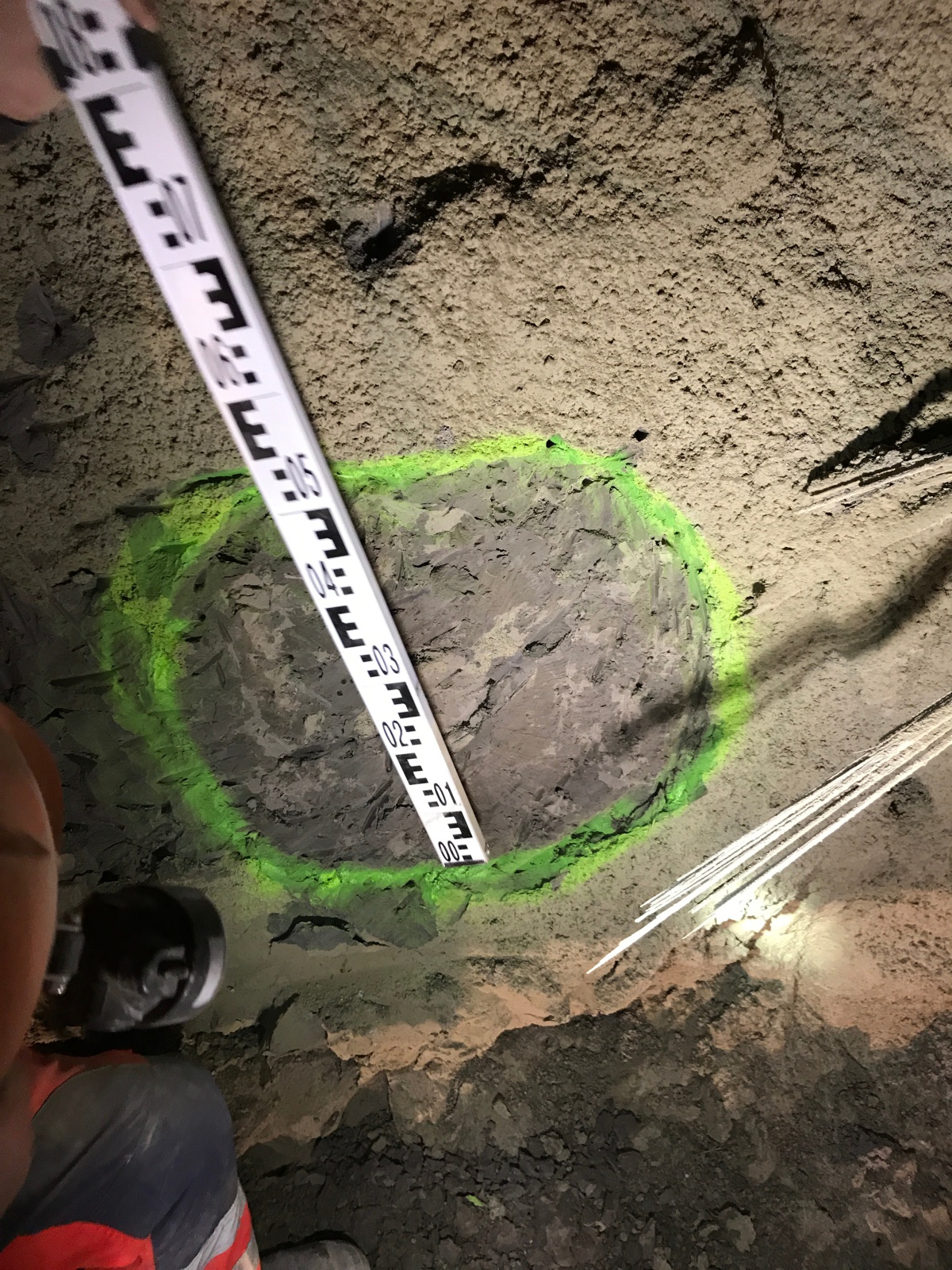
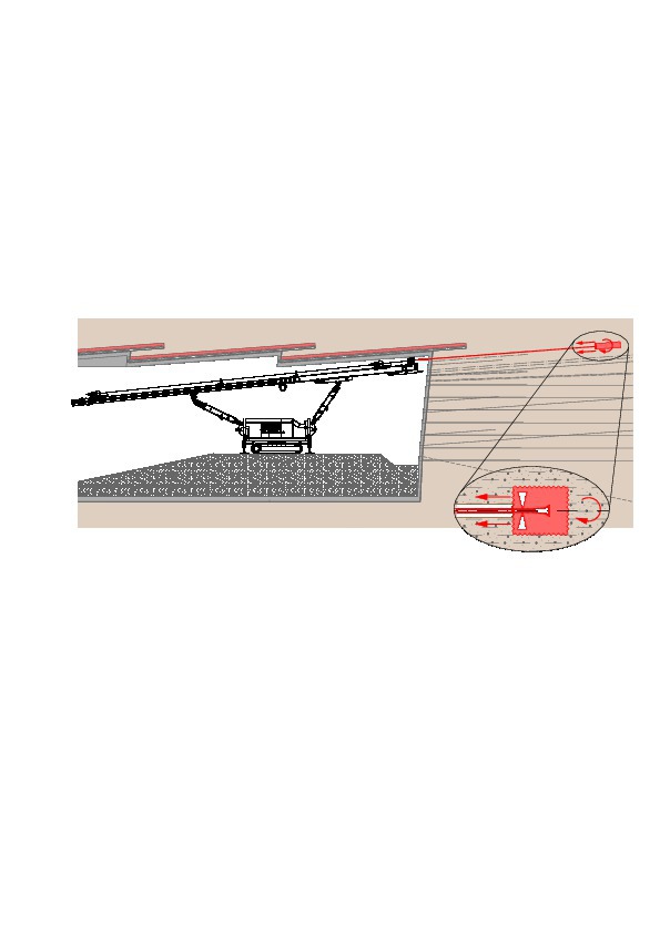
The main works of supplementary pre-support were the installation in stages of the horizontal jet grout screen in the spaces between the pipe umbrella pipes, which additionally sealed the inevitable longitudinal openings between adjacent pipes. The horizontal jet grout columns up to 17 m long were carried out with a two-armed drill rig with a 28 m long drill carriage in a single-phase system. The parameters were initially chosen based on values from experience in similar soil. During the first tunnelling stages, test columns were created within the excavation profile with various parameters for verification (Fig. 9). It turned out that diameters of 30–50 cm were practical in the clayey lacustrine deposits. Primarily sandy zones were grouted; compact lacustrine clay remained ungrouted in some places. In the gravel complex, the installed jet grout columns were as expected more homogeneous. Fig. 10 shows the sequence of installation of a horizontal jet grout column in three steps.
During the jet grouting work, all the buildings above were monitored in real time with survey chains (inclinometers). Above all where the tunnel is at a shallow depth, the jet grouting works led to measureable local deformations, mostly heave, of a magnitude of 5–10 cm depending on the prevailing geology.
5.3 Machinery
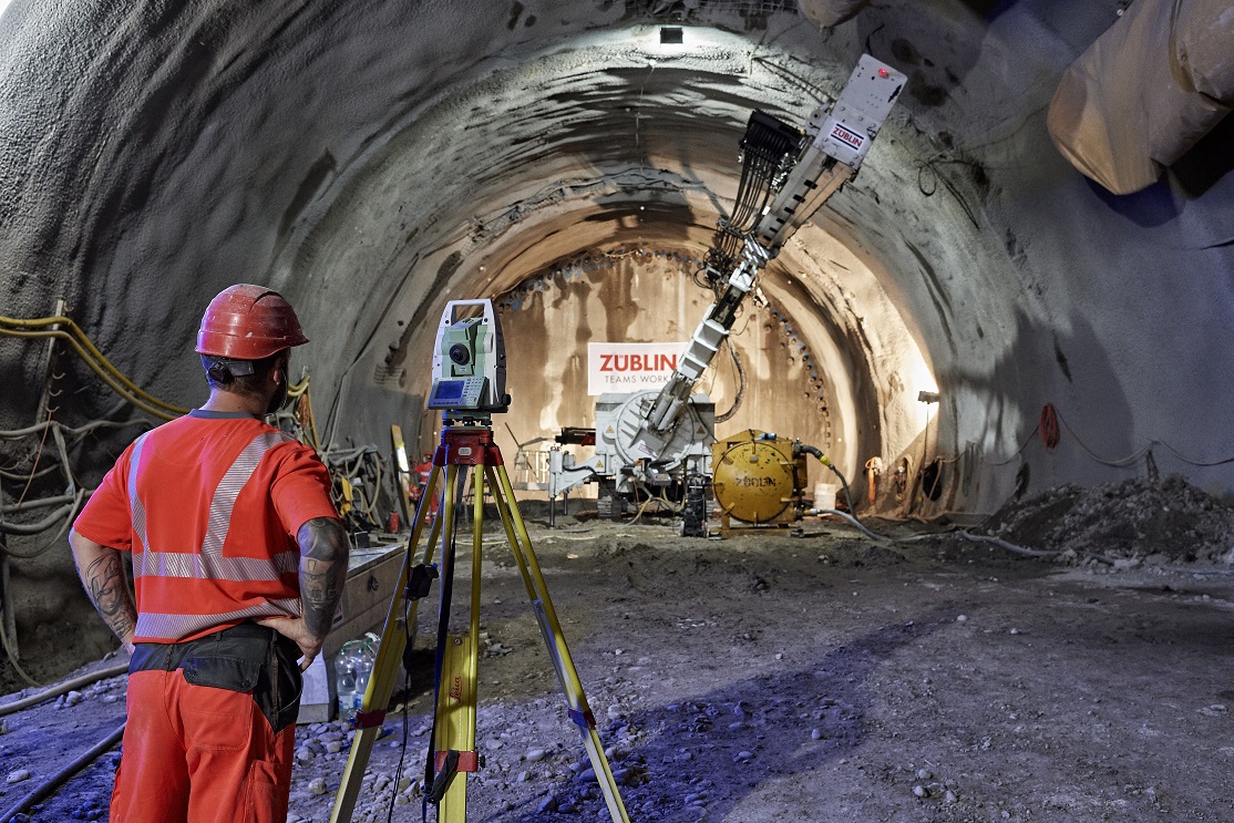
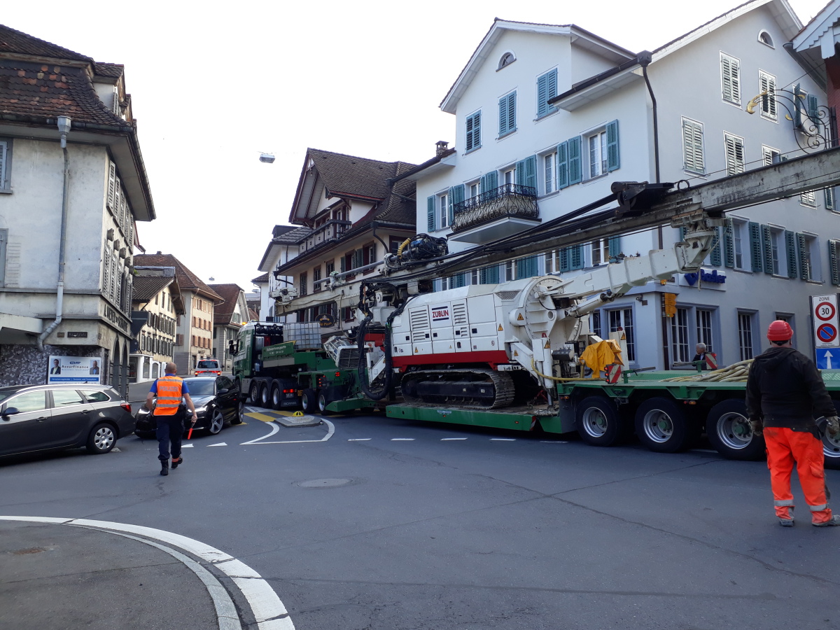
Due to the use of the horizontal drill rig with a carriage length of 28 m (which was appropriately lengthened for the project), all the drilling – horizontal jet grouting, drainage holes, grouting holes and face anchor holes – could be drilled in one run without adding drill strings (Fig. 11).
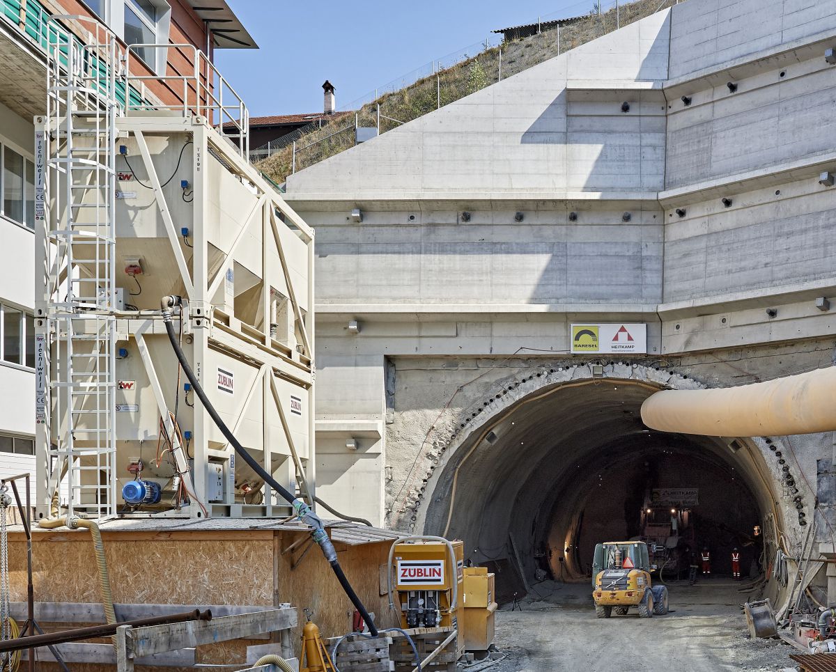
In order to optimise the overall construction time, the works were carried out simultaneously from north and south. Tunnelling works and jet grouting works were carried out alternately at the opposing ends. The machines had to be moved for this purpose after each stage (Fig. 12), but the necessary plant (high pressure pumps, mixing and storage technology etc.) was installed in front of the portals at both ends.
6 Experience of Tunnelling
and Conclusions
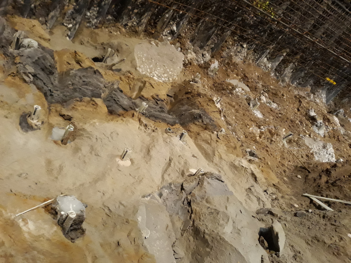
This special construction project in glacial geology has shown that complex geological situations demand very great specialisation of the support process regarding its nature and extent. The extent of the complexity in the glacial geology is shown impressively in Fig. 13 (fluid-pasty sandy silts, densely to very densely consolidated gravels, organic sands, peat and stiff to semi-solid lacustrine clay in a single face). On each advance stage, all the consistencies, consolidations and soils known to the geotechnicians, from densely to very densely consolidated gravels to fluid-pasty, sandy silts, were indeed encountered. This demanded intensive discussion between all project parties, especially between those responsible for tunnelling and specialised civil engineering.
In the performance of horizontal jet grouting in a shallow tunnel, great attention has to be paid to utility installations such as sewers, drain pipes, cellars and existing ground improvement or deep foundations. In heterogeneous soils, the differing permeabilities of the soil can lead to water passages in the subsoil, through which the grout can travel great distances and can even reach installations outside the immediate area affected by the tunnel.
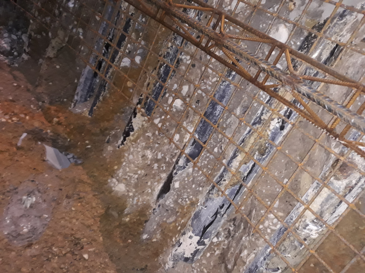
Therefore, it is particularly important for specialised civil engineering projects in built-up areas to involve the local inhabitants and affected parties at an early stage and that the surface monitoring is carried out at a high resolution in order to be able to detect the effects of tunnelling immediately. Regarding supplementing the support plan with the installation of horizontal jet grout columns along the perimeter of the excavation, it can be stated as a conclusion that the combination of pipe umbrella and jet grout sealing of the interstices can be carried out without problems (Fig. 14), although an appropriate extension in the toothed profile in the longitudinal direction of the tunnel should also be pointed out.